
Installing Front USB
Introduction
Our cases support front USB in two ways: 1) Via a pass through connection-Compatible with all mainboard with USB support 2) Via a port to header connection.
Pass through to rear of case
The ports on the front of the case connect to a standard USB cable. The cable goes from the front through the inside of case,then simply plug the standard cable into one of your back USB ports. On our Aluminium cases range we have a secondary attachment block which plugs into both the slot cover, and the back USB ports. The draw back of pass thru front USB is that you lose the ports in the back.
Front USB via a Port to Header connection
Ensure that the wires from your port will connect to your motherboard's header. To do this you need to know what header you have, and what type of connector you have on the wires.
A USB header is either a single or double row of header pins on the motherboard that can be used to add additional USB ports to a computer via the use of an appropriate set of header connectors, wires, and a USB port. Each pin on the header corresponds to a wire inside a USB cable. These pins must be clearly marked so that you can hook them up to the wiring correctly. There are 2 common layouts for a USB header.
Intel Standard USB header Layout: (used by over 90% of motherboards)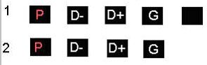
Gigabyte Style USB header Layout: (used most commonly on Gigabyte brand motherboards)
What the Wires Mean
All USB cables have 5 wires. 4 of these wires are actively used. Here's a reference from the official USB standard. 
On a front mounted USB port you'll have either the first 4 wires connected to properly colored wires (red for power, white d-, green d+, black for ground) or all five wires attached to the port (same as the former, but one extra black wire).
The wires are attached to a header connector using any one of a number of different types of connectors. Common types are listed as follows:
Common USB case header connectors
| 1) 4 joined pins + 1 extra ground. Compatibility: Compatable with both header arrangements because of the extra ground. |
| 2) All pins seperated: Compatible with every header. |
| 3) Power and Ground seperate, d-, d+ joined : Compatable with all common headers. |
| 4) All pins joined Intel style easy connector: Compatible with Intel standard only. |
| 5) All pins joined Gigabyte style easy connector. Compatible only with boards with a Gigabyte style header. |
Making the Connection
Now we need to connect the Header to the connection So look in your motherboard manual. Below you'll find a exert from a fairly recent motherboard manual for the Asus A7M266 motherboard. It's typical of a motherboard manual for a board using the Intel standard USB header. 
The first thing you'll probably notice is that the wiring from your case and the names of the pins might not quite match up name wise, so following is a summary of what might be found:
Power may be called: P, VCC, USB Power, Power, and PUSB. On wiring it's always red.
Ground may be called: G, GND, Ground, and GUSB.
D- may be called: USB-, USBP-, D-, or just -.
D+ may be called: USB+, USBP+, D+, or just +
From the diagram we see Asus decided to number the middle pins. On the first row (starting with pin 1, and marked with a 1) you'll find that they list D- as USBP2-, and D+ as USBP2+. The number 2 tells you a few things. First off: It's the 3rd USB port on the motherboard (they started numbering at 0), second it tells you that that D- and D+ must be used for the same port. Case manufacturers are just as likely to number their ports differently.
Notice that you're D-'s have either a 1 or a 2 on them. These also tell you that they are part of the same USB port. (Remember, 1 port has 4 required wires). The numbering on the connector and the numbering on the header doesn't have to match.
Connection the Headers
Take the following connectors: a same number D pair, (D-, D+), 1 power, and one ground. If your power and ground are numbered make sure all 4 are the same number.
Next, take your Power, D-, D+, and Ground and line the connector up with the appropriate 4 header pins on your motherboard. The header pins will be in a row under the Intel style, and in the Gigabyte style it will either be a row of 1 pin, a gap, and then 3 pins, or 3 pins, a gap, and then 1 pin.
Now take another set of connector wires (Power, D-, D+, Ground), and hook up your second front USB port. If your case has more then 2 front USB ports, and your motherboard has more then one front USB headers, then repeat the above as necessary.
Example: If you were hooking up the front USB on a A7M266, on a case with the pictured 4-pin joined connector type then: VCC lines up with USB Power, USBP2- lines up with USB1-, USBP2+ lines up with USB1+, and GND lines up with GND. For port 2, VCC lines up with USB Power, USBP3- lines up with USB2-, USBP3+ lines up with USB2+, and GND lines up with GND.
|
